poser 7 pro mechanical rigging basics needed
ill start with this as far as using poser goes i am a total idiot so far
i finaly got my objects into poser and scaled them and got them where i need them and i tried rigging them but since every single tutprail i can find is for rigging biological forms the methods dont cross over to me
ive had the software for too many years not to know it but until this weekend everytime i imported anything it crashed
so i am askin the 3d community for help
i am looking for some type of tutorial as to how to rig a mesh in poser 7 pro that even an idiot couldnt mess up
i have opted to learn on what has to be the most involved part because if i can learn that the rest will be basic
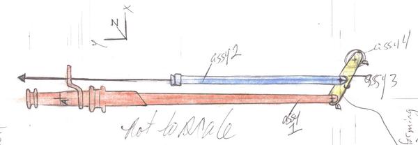
i will attatch a sketch of the 1st part of the mesh because i have not decided the fate of the 2nd part yet and if need be i can provide a simplistic version of the mesh for anyone who would help
any assistance would be appreciated since i normaly use blender only and this is all new to me and i am looking to package the models for sharing to poser, studio users as well


Comments
It's a little hard to tell what is meant to happen from that, but the first thing to remember for mechanical items is that you don't (generally) want them to bend, so turn bending off for all of the bones. If you do that, and as long as your assemblies aren't welded together in the OBJ, that should get you well started - just use the joint editor to position each bone's origin, and set the rotation order so that the first axis goes along the part and the one that turns most is last - that looks like y(long)x(no turn)z(pivot) for assemblies 1 and 2, xyz for 3 and it's hard to say for 4. are there any parts that need to attach to two places - is the arrow free, or is it constrained by the bit it goes through on the left?
i hastely cropped the sketch to make it fit here and dropped the details
A= the once fully rigged and parented center of rotation that would be almost loke a wheel around an axle
B= the point where all parts parented to assembly 3 will master rotate on a single axis
C= a control or follw point for aeey.2
D= the actual axle or center odf the wheel assembly not shown
the arrow looking part is actualy part of the model that acts as the cap for the springs that will be put into place later because i still need to figure out if i want to use conform or collisions
and for those not familliar with the designs it is a model that i made of a set of springer style forks for a motorcycle
on aasy 1 part of assy2 passes through a stationary plate that supports the springs it can adjust for the small amount of rotation from C
total rotation at A would be limited to a total of 12 degrees
OK, so taking each assembly as a bone you'd want the centre of bone 1 to be at A, the centre of bone 3 to be at B, the centre of bone 2 (which would be a child of bone 3) to be at C, and the centre of bone 4 to be at D (and that bone, if it's to be an axle, would have the rotation order zxy or zyx). You'd also, if I understand, want another bone positioned so that its centre was aligned with the arrow assembly, and bone 2 should then point at that to maintain its alignment as bone3 moved.
im starting to think that i might be overcomplicating things so i will post a pic of the object as modeled and with a color coded by group
the yellow lines are the centersof each part
This is indeed a weird machine, but it has linear motion driven by a crank, and looking at its rig might be helpful to you. (No nudity, but mature content at link)
http://www.sharecg.com/v/14580/View/11/Poser/Weired-Machine
wandw ive seen that before but with as little as i know about poser unless i made the mesh i cannot get it to show up or extract into the runtime folders
i might need to unistall and reinstall into the default location to do anything
i do have the on disk figures but thats it
ok a bit of history
used blender for almost 11 years
used studio 1 time
used poser 1 or 2 times , with no results
used bryce from 3.5 to 7
photoshop from 7 to cs6
richard i do appreciate the help so far but some terms do not relate from 3d to realworld and viceversa and i work with these parts everyday so i know the names while in 3d people dont work with vintage harleys normaly
i might be overthinking the simple here so ill go to PS and draw what i need to be able to do and post that
If you are having problems with installed content not showing up, it's likely (presuming you are using Windows) due to Windows User Access Control. The easy solution is to move the Poser directory from Program Files to the root directory of C:, then reinstall the Service Release 3 to that directory (telling it to keep your settings) which will reconstruct the file associations.
You should also create an external runtime (I don't install anything to the main Poser program runtime except Python scripts and Face Room heads) Here's how to set it up in Poser 7...
http://www.bellesgraphics.com/Classes/Extra-Lessons/Runtimes.html
I have over a dozen external runtimes containing various categories of content....