Test Images (and more) For IBL and Environment Maps - UPDATED AGAIN
 3dcheapskate
Posts: 2,720
N.B. If you are using UberEnvironment2 DO NOT PLUG A JPG IMAGE into the UE2 light...
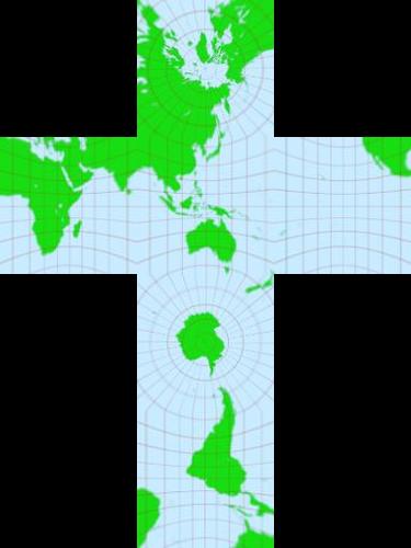
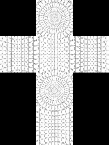
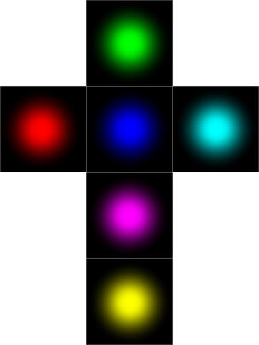
The first four postsin this thread each contain three test images - coloured spots, an az/el grid, and a world map from Wikipedia). This (the first post) has the vertical cross cubemap. The next three posts have latitude/longitude, angular map, and mirrored ball formats respectively. The lat/long worldmap is only 512x256, whereas the other two are 2000x1000 - in hindsight the colourspots image could have been made much smaller too).
Posts #5, #6, and #15 each contain a lat/long and angular map pairs created from a Terragen world. None of them are perfect (this is a learning exercise for me!)but hopefully they're getting better aswe go. If anybody else has created similar paired images feel free to add them to this thread.
Confused By The Terminology? I Found The Simplest Way Was To Sidestep It And Look At Pictures!
(or check here - http://www.hdrlabs.com/tutorials/index.html#What_are_the_differences_betwee )
Getting confused by all the terminology? Surely a sphere map and a spherical map are the same thing, but why is a spherical environment map actually rectanglar, and why is it usually square when it should be twice as wide as it's height, and are mirror balls the same as light probes and, and should I be using a light probe or an environment map for this IBL, and...
....aaaarrrgggHHHHH!!!!!
I read loads and loads and I was still confused, so I made my own test images and plugged them into the various image nodes/bricks in the Poser/DS shaders. It soon became clear what sort of map goes where. Since it helped me, I reckon it might help somebody else. So I've uploaded a few different mappings of my two test images here, plus a couple of pseudo-realistic environments in later posts. You can do whatever you want with these images.
Start Here
Imagine that you're Victoria 4, or Genesis, or Posette, or whoever, and you've just been loaded into DAZ Studio / Poser in the default pose. There are six different coloured lights around you, all pointing at you from different directions: blue from in front of you; red from your left; green from above; yellow from behind; cyan from your right; magenta from below. That's what the 'ColourSpots' test images represent - they're mainly for testing lights. The other 'AzElGrid2' imagines are simply an azimuth/elevation grid at 10° intervals (like the latitude/longitude lines on a globe or map of the earth - those are mainly for checking the orientation and alignment of skydomes, reflection mappings, etc, and to see whether you need to do a left/right flip to the image.
I used HDRShop (version 1, the free one, is still available - there's a link on the HDRLabs tools page here - http://www.hdrlabs.com/tools/links.html ) to convert between the formats, so I'm using the HDRShop names for the formats, i.e.:
- Mirrored Ball
- Light Probe (Angular Map)
- Latitude/Longitude
- Cubic Environment (Vertical Cross)
Cubic Environment (Vertical Cross)
Cube maps don't seem to be used a lot (at all!) in DAZ Studio / Poser. But they're probably the easiest way to visualize. There's two common variants - the vertical cross (shown here) and the horizontal cross (not shown).
Imagine the cube map image below (with the coloured spots) laid on the floor, with you standing in the middle of the magenta circle, looking forwards over the top of the blue and green circles. Now fold the box up around you. Do the same with the other box and it should be like you're inside a globe.
See the fifth post for notes on how to use these images.


Comments
Latitude/longitude
Also known mathematically as the equirectangular projection. It should be the most familiar to you because it's the way maps of the world are most often represented.
This sort of mapping is commonly used for skydomes and reflection maps (I think you may need to take a mirror image to use it for reflections). It's the same way a map of the earth is created from a spherical globe, except you look at a globe from outside, but we look at a skydome from inside.
This image is a useful test for skydomes and similar environments, and for reflection maps.
Note: skydomes often use only the top half of a lat/long image - you can use the az/el grid to check your skydome
Light Probe* (Angular Map)
The main point about this mapping is that the azimuth scale across the centre of the circle is linear (unlike the mirrored ball).
This type of image is often used to provide full 360 azimuth / 180 degree elevation environmental lighting.
It is distinctly different from a mirrorball (see next post). {Edit: However, it appears that when people talk about 'light probes' they often mean 'mirror balls'. Confusing...}
This is the most likely image to give you the correct results when plugged into any sort of light, although you probably need to flip it left/right first.
*according to HDRShop - see first post
Mirrored Ball
Mirror ball images are what you get if you take a real world photo of a real world chrome ball. They are NOT the same as angular maps. They're similar, but distinctly different. To add to the confusion they often seem to be referred to as light probes. It took me ages to work that out!
I read somewhere that angular maps can be made from real world mirrorball photos by taking two photos of the same mirrorball from opposite directions and then using software to combine them.
Note: All the test images in the previous four posts cover a -90 to +90 degree elevation range. Skydomes usually only cover a 0 to 90 degree range- use the az/el lat/long test image to check whether your skydome uses the whole height of the image or just the upper half.
How To Use The AzElGrid2 Test Images
For skydomes, etc: Simply plug any of the images (latitude/longitude one is most likely to be the one you need) into the diffuse/ambient/whatever channel of your skydome, set the camera in a known position, and render. Check that you're seeing the correct azimuth and elevation marks in the render.
For reflections: Plug any of the images (latitude/longitude one is most likely to be the one you need - Poser probably needs it plugged into a 'Sphere_Map' node first) into the reflection channel of your object and render. The text in the reflection in your render should be back to front - if not you need to left/right flip images for reflections. Also check reflections from different angles - you may notice something...
How To Use The World Map Test Images
I added these because almost everybody knows what this should look like
How To Use The ColourSpots Test Images
If you're not sure what sort of image to plug into your lighting:
1) Create a cube primitive at the centre of your scene (you want to be looking at the cube from outside - we're
2) Make sure the cube is plain white on all sides
3) Delete or turn off every scene light except the one you want to check
4) Apply one of these images to your light (the angular map is the best bet)
5) Position the camera so you can see the front, top, and left sides of then render. They should be blue, green, and red.
6) Position the camera so you can see the back, bottom, and right sides of the cube and then render. They should be yellow, magenta, and cyan respectively.
Here's the results of applying the 'ColouredSpots' angular map* to the UberEnvironment2 > Light > Color in DS4, and to the Diffuse IBL light in Poser 6. The left side of the figure/box should be red and the right side cyan - so that shows that the angular map image must be flipped left/right before being plugged into these channels. It also shows that the angular map is the correct one to use in both cases.
Hope that somebody else finds this useful. I did!
*N.B. That's NOT the correct way to use the UberEnvironment2! Follow the instructions here https://helpdaz.zendesk.com/entries/22131881-Beginning-Help-with-UberEnvironment-2 to use it properly. The UberEnvironment2 > Light > Color should (I think) be left white with no image.
Edit 2 (6Sep13): UE2 is badly flawed - there's offset problems with both the light and the environment sphere - check this 'uberEnvironment2 IBL map axis is wrong' thread, and this 'UberEnvironment2 - Can Anybody Explain The Result Of This Simple Test?' thread '
Here's an environment/light probe pair I made (not HDR*, just ordinary JPG). I set up a simple world in Terragen Classic, rendered the six views for a cube map, made the cube map in GIMP, and converted it to equirectangular and angular versions using HDRshop. The angular version is already flipped left to right.
Not perfect (you can see some black/white lines where the edges of the cubemap were) but it works quite nicely. Both images are 1024x1024.
If you want to add an infinite light for the sun to create some shadows it was 45° up and 45° right. The camera was 100m(?) above the water. There's a couple of test renders in my Art Studio forum thread here.
*N.B. If you want to create your own HDR images this way I'm fairly sure that you can (although I haven't tried yet) After creating the six renders from Terragen Classic, you do exactly the same renders again, but set the exposure lower/higher, so it picks up more detail from the dark/light areas. Do this for two higher exposure and two lower exposure settings. Then use HDRShop to combine the 5 exposure settings for each view into a single .HDR image. Then use CinePaint or similar (GIMP for HDR images) to combine the six HDR images you've created into an HDR vertical cross. Then use HDRShop to convert the HDR vertical cross to an HDR angular map. That's hat I've read anyway!
*Amended version of the above process. This one works - see note in post #15) After creating the six renders from Terragen Classic, do exactly the same renders again, but set the exposure lower/higher, so it picks up more detail from the dark/light areas. Do this for a few higher exposure and a few lower exposure settings (not sure exactly which T-Stop values to use I used seven - +0.0625, +0.125, +0.25, +0.5, +1, +2, +4). Using GIMP, etc combine the six renders for each exposure setting into a vertical cross cubemap. Extend the edges of the cubemap slightly to avoid those black/white lines appearing along the cubemap edges when you convert to lat/long, etc. Then use HDRShop to combine the 5 exposure settings for each view into a single .HDR image (I used the '1 F-Stop'setting, not sure if that's correct) . Then use HDRShop to convert the HDR vertical cross to an HDR angular map.
Same scene with a different sun/atmosphere/clouds setup in Terragen. Sun's straight ahead, about 25° up. Just JPG images, not HDR, same as previous post.
Very cool info and thanks so much for the test maps!
360° render in Blender Cycles using the Latitude/longitude (Equirectangular) Map
with a wider field of view we could see if the progection makes the cuve edges look squary
guess i should now do the same render in Daz Studio Uber2 huh? :)
-------------
figure 2, same scene in Daz Studio 3 using Uberenvironment 2
the Latitude/longitude (Equirectangular) Map was applied to
the light's color channel -- the env. sphere color and ambient maps
and i made the env. sphere "visible-in-renders" but make sure to leave it
to not cast shadows
the results are similar
i.e. lots of green light from the ceiling
when we're behind the Aikos, we see they get much red light from the red wall
----
note that this does not yet prove that the equirectangular map matches the light-shader projections
Thanks Casual - I think your post was intended to go on the other thread!
The lighting still doesn't seem right to me - you see the red, green and cyan on the cubes you have scattered around, but you don't see any yellow or green? Did you have another light in the scene - or it could just be the camera angles.
And I'm also curious why the vertical white lines from the environment map don't line up with the corners of your ground plane (although that's a completely different issue!)
P.S. sorry to be such a PITA! ;-)
Deleted post . If you saw the latitude/longitude test map images here while I was editing, you'll now find them added to the first four posts.
i think the corners of the ground plane would meet the white lines of the IBL if the camera was at position 0,0,0 and if the plane and the environment sphere were very large
for the cycles render, the tints are hard to see because Cycles computes many ray-bounces, and possibly because the objects were too glossy, but when the camera is on the red-light side we see a ren tint on the faces of the cubes facing us
the green comes from above so the floor and the pyramid are greenish but since they also "see" the red blue cyan and yellow its a grayer green
as for the yellow, which should be most visible at frame 3 and 4 ... we kinda seem to see it on the Aiko's arms but the cube faces facing us look green-gray, which could indicate that many light colors are visible on that side of the universe used by the renderer ... instead of one big yellow blot
to better see this a polarizing trick would be needed , like light going through long tubes or parallel planes and a camera obscura
yay it worked
i built the polarized projector
rendered 32 test images
and am able with a high degree of confidence
to say that UberEnvironment 2 lights in Daz Studio
use Lat-Long Equirectangular maps
not sure wgy yellow is so faint though
I'm so glad I only said I was 99.9% certain it should be an angular map! Your Polarizing camera obscura rig, plus some instructions I found here https://helpdaz.zendesk.com/entries/22131881-Beginning-Help-with-UberEnvironment-2 make me realize I'd made a stupid error!
(But luckily saying I was only 99.9% certain still leaves me with that 0.1% get-out clause, soooo ... )
Okay, I put my hand up! I confess! I was wrong!
:cheese:
...again!
D'oh!
well i must admit i'm 99.9 percent confident of my results since there was a peep-hole in the room's wall ( which i later found was not needed ) which could've leaked light. and i had to make the Env. light 1000% bright to get something coming through the poarizing tubes
thing is, i'm sure in the old forum's archive there were night-long debates about all this :)
(Just in case you hadn’t noticed, I’ve changed my display name from 3dcheapskate to unrealimperfect - just trying it out… it’s already had me confused, so I added a note to my siggy too!)
Another environment created in Terragen Classic and converted with HDRShop.This time I sorted out the edges of the cubemap before converting so there aren't any spurious black/white lines on the images. Sun's 45° up and 45° right from centre-point. Camera's only 2 metres above the ground, so around head-height.
The lat/long map is TgEnv02LDR-LL(2000x1000).jpg and is 2000*1000 pixels, 338KB (the original was 4096x2048, but the forum limits images to 2000x2000)
The angular map TgEnv02LDR-AM(1024x1024).jpg and is 1024x1024,156KB
I also tested out the procedure for creating HDR images in post #5 and it works! I've ended up with a jpg/tif/hdr set that work nicely with the UberEnvironment2 (although I think my terrain colours were too bright in Terragen, still, live and learn...).
But I noticed that the 'Set HDR KHPark.dsa', etc files for applying images to the UE2 all have a copyright notice including...
...so I can't just edit the g_sMapName and sBasePath variables and upload a modified version with my images. So what's the official route for obtaining permission?
~~~~~~~~~~~~~~~~~~~~~~~~~~~
I'm currently playing with a DIY Diffuse IBL for DAZ Studio (yes, I know UberEnvironment2 does that (and far more) already, but I like tinkering) along with an all-encompassing background sphere (yes, I know there's plenty of those already) and a simple morphing terrain (ditto). Once I've got that all sorted I'll be uploading proper full-size versions of the environments here (plus HDR versions for UE2 if I can get permission!), plus the Terragen tgw and ter files (if I still have them...