Daz Studio 4.6 Pro - Figure Setup - Geometry Not Sticking To Bones
 Lord_Ashes
Posts: 91
Lord_Ashes
Posts: 91
I am trying to follow some Figure Setup tutorials but they are all for previous versions of Daz so the process is a bit difficult to follow.
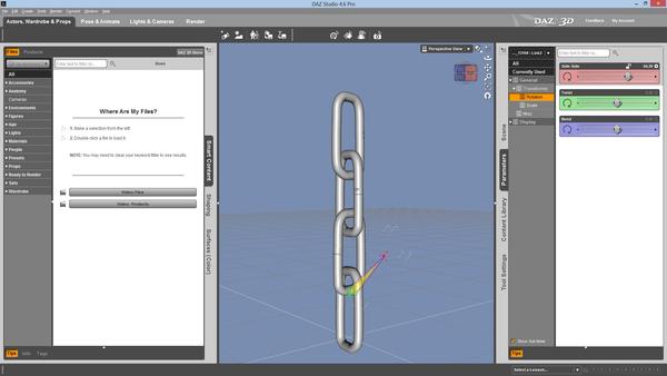
I am trying what I thought should be a simple figure/bone example...I have an chain object which is made up of 4 links. I would like to bone this object so that I can manipulate the links in the chain but still keep the chain together.
This is what I did:
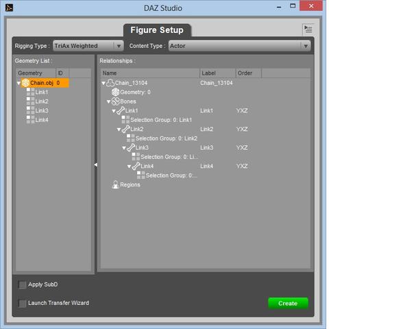
1. Using Figure Setup, I loaded my geometry.
2. Next I dragged the geometry to relationships to generate bones for the geometry items.
3. Lastly I dragged the resulting sibling bones so that they became children of each other.
My thought on that was if one link is rotated 90 degrees (or similar) it needs to affect (displace) all following links - hence the children relationship.
See screen capture 1.
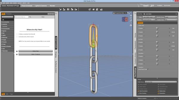
4. Next I used the Joint Editor to set the Center and End point of rotation.
See screen capture 2 and 3. The screen capture only shows setting the first and last link but I did all 4.
5. Next the tutorial goes into setting the Bend, Twist, etc parameters but this is where I get stuck...
The only option offered, when I have one of the links selected, is Center/End point. There is no option for bend, twist, etc.
6. If I try using the Bend, Twist, etc parameters of the link, without setting the bend, twist, etc limits then I don't get any
reaction from the link geometry (as if the geometry was not linked to the bone at all). I am not sure if this is because
the geometry is actually not linked to the bone or because the bend. twist, etc limits are set so that everything is in the
red (non affected zone).
See capture 4.
Can anyone clue me in as to what I am doing wrong. As soon as I can get the links bending and twisting then I should be able to figure out where I need to place Center/End points in order to do what I want but at the moment the geometry does not follow the bone at all (except for the first link...and I am guessing that is because of the parent/child relationship and not because of actual joints).

Daz 3D is part of 
Connect
DAZ Productions, Inc.
7533 S Center View Ct #4664
West Jordan, UT 84084
Licensing Agreement | Terms of Service | Privacy Policy | EULA
© 2025 Daz Productions Inc. All Rights Reserved.
Comments
you set type as triax figure, in figure set up tool.
so that if you want to follow your mesh with rig, you need to color weight map (triax or general)
after you set rigs. you may need to change tool to color weight map brush,
then color weight for each node of rotation (scale) .
Or you can change RIgging type as Parametric (leagcy),
it can auto assign bone with same group named mesh part,
then each mesh move with the rig.
(eg your Link1 mesh move by link1 node)
you can use bend option, select the node and go to parameter tab>Misc,
you may need to set "off" about each node, so that the joint area not bend.
(though I do not know,, if it need or not about your chain,^^;)
And you may need to export the figure as cr2. to save the figure.
Because only weight map figure can be saved in ds 4.5 as figure and prop .
then if your geometry scale is not much as poser scale,
(if your geometry.obj was not imported as poser scale option,, )
after export cr2, you may need export geometry with poser scale.
and overwrite the geometry obj which copied in your runtime/geometry.
Or you can save it as scebe subset,, but you may hope to save it as cr2
to keep the geometry data in your clear named folda runtime/geometry/
You need weight maps to tell DS what mesh should move - in this case that should be quite simple. Select Link 1 and switch to the Weight Map Brush Tool. In Tool Settings, Select one of the rotation maps in the Unused Maps list, then click Add Map; repeat for the other two maps. Select one map in the list. Right-click on Genesis and from the menu choose Polygon Selection>Select>Face Groups>Link 1. Right-click again, select Fill selection, and set the value to 1. Repeat for the other two maps. Right-click one more time, Polygon Selection>Clear selection. Then do the same thing for the other three links, using their group each time of course. That should be it.
Fill weight by selection set may make more easy to color weight.
set tool weight map brush,
then select the figure in scene tab,
then r-click in 3d view,
choose select one of face group.
then r-click again,
Fill weight by selection set.
it auto add weight map, and fill weight X,Y,Z,and scale,
about each face group with 100%.
I accidentally Fill weight by selection set, to follow this topic,
Now it auto color about other node of X,Y,Z,and scale,,,with 100% weight,
for every face group @@; thank you much.
Yes, I always forget about that.