Corrupted model? / shiny surfaces looking ugly
I am relatively new to 3D modeling and I've had trouble with the combination Hexagon and DAZ Studio for several times with the same issue:
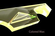
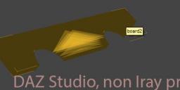
In Hexagon everything seems alright, but in DAZ Studio a plane surface of the object looks very ugly. You can see it in DAZ studio already in non-Iray-preview when highlighting the object. And in the final Render the result is okay for smooth shaders like carpet, but bad with shiny shaders like metal.
Are non-planar polygons the reason? Or is the obj-file corrupt?


board asphalt.jpg
1236 x 750 - 182K


board carpaintgreen.jpg
1236 x 747 - 81K


board coloredwax.jpg
1236 x 815 - 138K
zip

zip

board2.zip
16K


hexagon.jpg
857 x 422 - 57K


DAZ Studio preview.jpg
622 x 206 - 27K


Comments
I think the issue is that middle section where you have n-gons(polygons with more than 4 sides). Daz Studio doesn't like n-gons, and tries to fix them on its own, but the results usually don't look good.
I tried splitting the center n-gons on your model with Free Tesselate, and it helped a little but still had artifacts (board 3 in the images). Then I used the Extract Edge tool on the exterior edges. The result looked a little better, but now has artifacts along some of the edges(board 4).
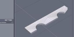
Image 2 is the wireframe in Daz Studio, image 3 is the regular preview, and image 4 is the Iray preview.
I'm still a beginner at Hexagon, so someone else can probably do better. Hope that helps.
I think @Kitsumo is on the right track. Getting rid of the n-gons is the first step. You can find them in Hexagon by using the Select menu and choosing "Select faces with more than 4 points".
You may also have some flipped normals there. This is when the direction a specific face is pointing is the opposite direction from the rest of the surrounding geometry. It might look normal, but you're actually seeing the "back" of the face. You can check for that using the "Orient Normals" tool.
Thanks for your help!
You were right. And even the automatic function "Triangulate N-gons" in Hexagon does solve most of the problem. After that the preview in DAZ-Studio with highlighted object ist alright.
I have checked normals orientation, but everything was ok there.
Another thing I found out: The points on the upper side are not all on the same y coordinate. I marked all the points on the top side at once and then in windows properties there was a value slightly bigger 0 for size. Changed that to 0. And repeated this process for the other sides as well.
Attached picture: first model is original (bad) model, 2nd is with resolved n-gons, 3rd is with "fixed hight values" for the points.
There is still one error left in the 3rd model as can be seen in the picture. Can't figure out why... Also attached this 3rd model as obj file to the post.
Would other modelling tools also cause so much trouble? Especially when using boolean operation? Up to now I only know Hexagon, but I'm kind of frustrated because of all the workarounds for just a simple thing...
I'm not sure why Daz Studio behaves that way sometimes. I run into it every now and then. Never have found a solution for it.
I think Hexagon's Boolean function may be part of the problem. It always gives me wacky results. I've stopped using it because it was so unpredictable.
Yes, no matter what polygonal modeling application you use, you will get this problem when using booleans. Booleans are challenging to use even on the top pro-grade application. Once you learn how to clean up the geometry, booleans in hexagon work fine. But, It is not a beginner method, so I would suggest you start with the basics first. Making this shape without booleans is relatively easy to do, but it's hard to explain in a quick post. Basically, you start with half a cylinder, copy that to make the other, connect, and extrude the edge to form the rectangle shape and then bridge to fill shapes between. Or, you could start with a single polygon and cut holes into it, then use the thickness tool to give it depth.
Okay, I start with to half cylinders (separate objects). Then weld them into one single object.
What does "connect" mean: Do I manually have to draw facets? First facet between points C-D-H-G , etc.
This mesh is an exaggeration. But at the end of the day, you want even polygons for the surfaces.
Nice. Did you do that by hand or is there a tool for it?
Of course I would also like to know, how you were doing that!
Why should the surface have a mesh? I thought, the goal is as few polygons as possible.
Also I guess, you used Extract Edge like Kitsumo did. Is this a "must", or just to make the edges a little softer?
A trick I've been using for a long time is that if you need a hole, start with a hole:)
For instance, on this one I started with two semi-circles, extruded, joined using bridge, extruded and once the shape an geometry were OK, added thickness. This has many advantages, such as only having to model one side as well as getting perfect arcs with good geometry.
Not just a trick you've been using. This method is regularly recommended. Problem being, people have difficulties visualising their model if they don't start the other way around so they tend to ignore it.
You are so right - this is where proper planning comes in.
Possibly a subject for a series of tutorials - how to go about examining various types of model to decide on the most appropriate approach. For instance, many models lend themselves to one of Hex's most powerful techniques, surfaces modelling, yet this technique seems to be seldom used.