Mesh change between Carrara and Daz3D
 lulamfada
Posts: 71
lulamfada
Posts: 71
This may be a problem that others have had and it was answered. I did not find such a message, so forgive me if this is a duplicate and if so, a link to the answer would be appreciated.
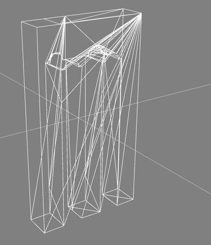
I am a relatively new user to Carrara, but have been using Blender in the past a bit, so not entirely new to 3d object creation. I am trying to create a table and ran into an odd issue. I wanted to do some checking that my UV was working relatively well when I move from Carrara to Daz3D and found when I look at the mesh in wire frame in Daz3D it is looks like the mesh is different. It goes from being a relatively nice mesh in Carrara to having extra edges added in Daz3D. I have tried a number of times and it looks almost like the mesh is getting shattered.
Has this happened for others?
Is there something odd going on in the obj export?
Any suggestions would appreciated
I am putting in two pictures to show what I am talking about. I am not suggesting that my first mesh is beautiful but it is an example I have saved and shows what I am talking about.
Thank you.
Daz 3D is part of 
Connect
DAZ Productions, Inc.
7533 S Center View Ct #4664
West Jordan, UT 84084
Licensing Agreement | Terms of Service | Privacy Policy | EULA
© 2024 Daz Productions Inc. All Rights Reserved.
Comments
All 3d apps reconstruct obj meshes to their own approach - so while the vertices will be at the same coordinates, the coordinate scale, subdivision, the sequence and smoothing may differ between apps. Its to be expected. There may not be much difference when rendered.
HI and Welcome :)
This is the conversion of Polygons to Triangles, either on export from Carrara, or import into DS.
Unfortunately the main problem with the "legs" is caused by your model.
the first leg, is a square,. (four points) the other two have five for some reason, so there are N-gon's and Tri's in there with Quads.
most programs will try to correct the faces of an object and respect the edge creasing,.
sometimes if your object isn't made correctly, the this can lead to an edge being extended to it's next relative point, which is why some parts of the legs are crossing over, ..hiding the arched sections.
Build using quads whenever possible,. keep the object definition as regular as possible,.
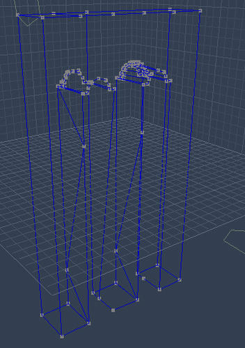
here's a quick and nasty example and wire-frame view.
Hope it helps :)
Your middle leg has the top corner joined to the middle of one side. This is creating a non-planar polygon (i.e. it isn't flat). Studio and Poser can barf over non-planar ploys, so you need either to correct the mesh, or triangulate non-planar faces in Carrara before you export (if it's deliberate).
The tris on the other legs suggest to me that maybe there's some twist built into them too.
Doing like 3DAge suggests and keeping to regular quads wherever possible will help spot issues like that, as well as keeping the model neat and tidy.
Thank you everyone for your suggestions. If I am understanding correctly, I need to make sure that I either have quads or triangles if I want to avoid having Daz break the mesh up itself. If I avoid other types of polygons beyond those, I will have less trouble? Again thank you for your help.
This leads to a second question, which might be best put under a different topic. If so, let me know and I will do so. The question relates to the suggestions that you all so helpfully gave. I was trying to alter the mesh a bit in Carrara to create clean quads or triangles and I ran into something. It is not possible to connect points that are not on the same polygon? It is what the help manual seemed to indicate but I wanted to make sure I was understanding correctly.
To give a bit more background on the mesh I showed, it is the result, at the curves of a boolean intersection. That is why it is so messy looking. I want to make sure I am understanding correctly that if I use such an operation and I get a messy mesh, does that mean I can not fix it in Carrara if it requires me to link points that are not on the same polygon?
Thank you again for all your help and guidance in moving from Blender to Carrara. :)
HI lulamfada :)
Carrara has all the tools you'd need to "fix" those boolean mesh errors,
but,.. sometimes,.. fixing broken things takes more time than starting again,..learning what went wrong in the first place. and learning from that.
Boolean operations can be a really useful modelling option,. but it's a "Power tool" of the modelling tool-set,. it forces the resulting model shape, and unless you set up both objects very carefully, it can easily create undesired results.
The model you've shown isn't a complex shape, and it's possible to model this, without using boolean subtraction.
you could extrude it from a box, or a rectangle shape, in the Vertex modeller,. or use the Spline Modeller, to draw the shape and give it depth.
Hope it helps
Thank you again for your reply and your guidance.
I was trying to keep my question clear and simple without giving too much detail so I did not make the question confusing but here is what I was trying to do and realized it led to questions that had less to do with this project and more to do with any project.
I am trying to do make reproduction of a table with precise measurements. The object I showed was the side of the table that needed a specific shape cut out by a a shape I created. I was trying to make all this easier not more difficult. :) It led to the problems I showed. What I tried to do was erase the bad edges and points, and then recreate by simply connecting the points I had left to create a better mesh. That was when I found that I could not directly connect two points that are complete apart, with no polygons connecting them. This is something that Blender can do so long as you are working on the same polymesh. No polygons or lines needed between the starting points. When I looked at the documentation of Carrara I think I understood that what I wanted to do is not possible. My struggle in the ending is not that I can not add a polyline or a point but rather I can not do it in the place I want numerically.
As a side note, I do know that you can look at the coordinates of the points but I had some trouble with that because the coordinates were incorrect. When I say incorrect, I mean I made an edge that six inches but because from what I can tell, since the vertex object started as five inches, it would never allow a coordinate longer than five inches. I suspect I am doing something wrong in all this that I have to figure out, but that is why I am not just making points and then moving their coordinates because right now, I can not get it to work. I am trying to solve one problem at a time. :)
This was a rather long explanation and I hope was not too confusing. I will ask this question because it really is my question I realize.
If I have a poly mesh and I delete many of the lines and polygons, so that I have polygons and points that are floating in space, can I directly create an edge between the points? The manual made is sound like I could not but I might be confused.
Thank you for all your help.
Sounds like you might do better using a polyline to make the profile and a coons surface for depth.
The problem with that route is that you still have to determine where to split your n-gons.
If you're planning to have this to be something that can be used in other software, and even more so if you intend to sell it via DAZ 3D, you want to try and keep to quads as much as possible. DAZ 3D does not accept meshes that include n-gons, if their policies are still the same. But beyond that, as said earlier, different software might read them differently.
In Advanced Carrara Techniques, Phil Wilkes does a beautiful job of teaching us how to set up and use template images to model on within Carrara, so that we can use the image's dimensions as we model. The problem in this example is that he does so as Tim suggests - using poly points and connecting them.
But the principle works the same if you were to start with a cube and model via extrusion using the image as a guide as well... the magic for me in that lesson (building an airplane: Sopwith Camel Bi-Plane!)
I agree that the object has a specific shape (all objects do),. but it doesn't have to be made by using another object to cut out the shape.
it can be easily modelled, and the sizes of your model can all be adjusted to suit whatever you need.
If you're building a Multi-part Object,. then it's easier to build (and fit) all of those parts (poly-mesh objects) as a single Vertex model.
I'd go with confused :) or just,.. unfamiliar with the carrara tools and options.
Carrara is a Modeller, and as such you can create any model your imagination will allow, and in many different methods.
If you have existing vertices, "floating in space", then you can take the Polyline tool and when your mouse cursor is "over" a vertex, the cursor icon will change to show a "Plus", .. which means that it has "Snapped" to that vertex, when you click and move to another vertex, you'll be drawing an edge from the first vertex to the next,. If you continue drawing a polyline around several vertices and back to the starting vertex, you'll create a face, or polygon.
Note: this isn't an ideal way to build any object ,. but you asked if it can be done that way.
using conventional modelling tools such as Extrusion, is a much faster and easier approach to rebuild your model.
Hope it helps :)
Note: Some tools, like Dynamic Extrusion, have "Snap to Grid" check box available. Otherwise:
View > Snap to Grid
I keep saying this but I truly mean it. Thank you all for all your help. I need to look through your answers and figure out what I understand and what I do not and probably ask more questions based on what you have said, but I wanted to address my question about using numbers for vertices.
A quick side note, thank you for explaining about using the polyline to connect points that are not on the same polygons or are floating. I was trying to do this with the link tool and failed, and that is when I saw in the manual that it said you could not create an edge if the points are not on the same polygon.
I am putting in four pictures to show the trouble I am having. I hope they are in the correct order. I could not get a picture that showed the numbers in the boxes, so I am listing them below.
The coordinates of the point that is selected in picture one is
1.77, 1.44, 5.00
The coordinates of the point that is selected in picture two is
1.27, 1.44, 5.00
The different being about .5 inches. The problem is that the length is 6.25, and since it is split into ten units, it should be .65 not .5
The coordinates of the point that is selected in picture three is
1.77, -3.56, 5.00
The coordinate of the point that is selected in picture four is
1.77. 10.06, 5.00
The problem with this is two fold. First, I told it to extrude in the offset box by 6.5 and it appears to have set the coordinate at 13.5 distance. The second problem is that, the length of the line that was created was not the correct length.
I hope that my pictures and explanation makes sense of the problem I am having. Please let me know if I should be breaking these questions into separate topics here. I am new to the forum and am not sure the way that is desired.
I model differently that this. What do you mean "I told it to extrude"? Are you using the dynamic extrusion tool?
If you select an edge or polygon, and have the Scale Tool selected, you may enter in exact amounts along any of the three axis in the panel on the right.
I should also mention that you may enter any unit of measure you like, even if it displays something else. In the "Units Example" in the illustration, notice that the current unit is set to 'Feet' (Ft). I enter in 55mm in the box under "A", and when I hit Enter, the results are shown in the box below "B" and the example of the change is shown to its right.
HI lulamfada :)
Firstly, the "offset" in the extrusion options doesn't set a "standard unit" for each extrusion,. it's an offset value from the original selection. ...you should normally leave this at 0.00 (no offset)
The Extrusion, is a Dynamic tool, meaning that you draw with it to create extrusions, rather than using numeric values to achieve a fixed regularly spaced extrusion.
Hold "Shift" or "Ctrl" to restrict the extrusion to Horizontal / vertical ..from the selection.
Any part of you model can be Moved and / or Scaled,.. to position your object in the correct place,.. and to make it the size you want.
whether you're working at 5 inches, 5 Feet, or 5 miles,. makes no difference to whatever object you're modelling, or the functions you use to create it..
Any model can be scaled to whatever dimensions you require. whether you're adjusting each extrusion as you work,. or adjusting the shape, or scale, of the final model
as Dartanbeck pointed out (above) ... you can enter any abbreviation for a value,.. EG: cm (centimetres) , in (inches), mm (millimetres), mi (miles), regardless of whether is your "working unit scale" is set to Metric or Imperial (metric or US)
Carrara will convert the input value, to your working units.
You can also adjust the size and "unit scale" of the working "Grid", and optionally enable "snap to grid"..
For example:
If i set the Grid size to 1 meter, and the division unit's to 1 millimetre,. then I enable "Snap to grid",.
this allows me to draw a square which is 1mm x 1mm, and if I extrude that square,. as I pull the extrusion out, it'll "Snap" to each 1mm of the grid .
Hope it helps ;)
Okay, so I'm not missing some different extrusion method... gotcha. Yes, I use 'snap to grid' as well, when I need to make uniform extrusions. And you don't have to stop at any one grid placement either. Say you've got the grid set to 1 foot, as default in a medium scene. Snap to grid will restrict your dragging to one foot increments, so if you only move your cursor a little bit, it will appear that nothing is happening until you get close to one foot, then you will see an extrusion. But if you need, say, a five foot extrusion, then just count out five snaps in the same drag, and you'll get a single five foot extrusion.
Another feature I often use was mentioned above by 3dage: holding down either Cntrl or Shift as I drag (extrude). This keeps everything uniform along the given axis, which is often very helpful.
Thank you all for your help and guidance. I am going to return to the drawing board as it were, and use the suggestions that you have given me to create some things and see what problems I get. :) I really do appreciate your guidance in this and look forward to making many things in Carrara. It is a really well put together program.