crunched up UV's
 dot_bat
Posts: 373
dot_bat
Posts: 373
why are the uv's crunched up on the inside polys? I have tried several mapping alternatives and cant fix it. such a simple mesh and im stumped. any help much appreciated
uvs.png
662 x 516 - 47K
Daz 3D is part of 
Connect
DAZ Productions, Inc.
7533 S Center View Ct #4664
West Jordan, UT 84084
Licensing Agreement | Terms of Service | Privacy Policy | EULA
© 2025 Daz Productions Inc. All Rights Reserved.
Comments
The UV mapper in Carrara is quite buggy - particularly if you're using cylindrical etc mapping - you'll find that one of the faces has been stretched across the entire map.
I now define seams and do a full unwrap on pretty much everything, even a simple cube. It's much faster than trying to figure out & fix up what the hell Carrara has done, and the results are a lot more predictable.
thanx Tim_A. Pins and seams it is then
I'll highlight the problem polys and see how they show up in the UV grid, from there I may choose a different projection mapping for them, detach them or both. For really problematic ones, I'll just create their own domain.
Would this be considered a bug? Im not very familar with 3d enough to say this is not the correct behavior or outcome. Is it my model? ive tried different modelling approaches and same result
creating separate domains and fitting each is my approach too, if it is good enough for Daz and their figures it suits me too
I don't think it is a bug. From the questions and such you see around here, UV mapping is a bit of a chore in most programs. I think Carrara generally does a good job of applying it's own internal UVs. I only do a UV map if I'm having some area I don't like.
Yes, it's a bug. I've reported it, had it verified and got a reference number for it... somewhere.
(which is no guarantee it'll ever get fixed!)
thanx tim_A and all others. ive tried detaching those polys, seperate domains, and it still persists.
Could you do us a screenie of UV view, with the problem ploys selected? It might help...
It can be a lot easier to UV map a mesh that is not quite so much of an n-gon. Meaning: the whole upside-down 'u' shape being a single polygon is an n-gon. While that would make that face a simple job with a planar projection operation from the perpendicular axis, if it was made up of simple quads, an unwrap method of the whole thing would be easier for the software to decipher.
I could 'show' you an easy method to edit a planar projection to get a uniform result, but putting it to words gets a bit more difficult for me. Basically, though, it would be a task of selection the edges on the left (mesh) window (from those that would result in an overlap, causing infinite stretching) and moving them in or out, depending on whether it's the inner or outer border selected, withing the right window (UV Mapping window).
If this is not solved by the time I get the time, I'll see if I can make a quick video.
thanx dartanbeck, i will be away from my computer for a few days.
Here is a thought, but is PITA. I suspect my suggestion is just a more primitive version of what Dart alluded to, but I will post so there is something until he gets time to illustrate.
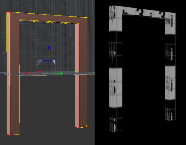
First, it appears that you have not modeled as quads. I'm not sure how much it matters, but I did my similar model as quads. I duplicated the model so I could illustrate 2 different uvmaps methods.
Left side - When I uvmapped the model on the left, I simply highlighted all of the polygons and then chose the custom uvmap "box" choice with 6 faces. The resulting uvmap literally maps the polygons to boxes, even if the model is a rectangle. The result is "scrunched."
Right side. When I uvmapped the right side, I assigned separate shader areas to the front faces, back faces, interior, and exterior. I then chose the front faces and then used custom uvmap with the "planar" in the y-axis. The result more closely preserved the rectangular shape of the legs of the frame instead of scrunching them in a box. I then used the front frame as a reference for the other shader areas. That is, I could use the box uvmap for the interior zone, and use the length of front frame as a reference to adjust the uvs of the interior.
In the attached render, you should see that the checker shader is less distorted in the model on the right than the model on the left.
EDIT: to see the biggest difference in scrunching, focus on the inside and outside faces of the models, not the front faces.
As I said, for anything complicated, this could become a big PITA, but didn't take too long for the relatively simple shape in the example.
Similar in concept, to be certain... bravo on that. I tried that a few times, wishing that there was a way to more easily have adjacent polygons remain adjacent, for ease in texture-matching. So the projection method I've eluded to is sort of the same, except that instead of having too large a projection that needs to be reduced, we end up with too small of a projection which must be enlarged, while all adjacent polygons remain adjacent.
It's a tip I picked up on from enjoying watching some of Andrew Price's (Blender Guru) YouTube (free) tutorials. Special thanks to my buddy Roygee for introducing me to Andrew. His tutorials may be for Blender, but they're excellent and fun, no matter what software is used. He has more helpful tutorials on other things as well, like color and composition. He's quite the insightful, young chap!
Where diomede's illustration says: "Used for reference", I also use that as a reference. But the inner and outer edges would also contain the edges for the perpendicular polygons. So one of the inner edges (one side only) would need to be reduced by that same measure, while one of the outer most edges (one side only) would need to be expanded by that same measure. This basically makes it easy to use a planar projection and then edit the perpendicular polygons. Certainly not the great answer for hi-res meshes, but for simple things like this, it can become a very quick and simple approach to an excellent UV Map.
On that note, some simple meshes are also very easy to simply use Unwrap, as mentioned earlier. If the unwrap comes out funky, add some seams first - think of it like the inverse of making a paper model.
These are very important concepts to practice and get squared away in ones head. We need to know how we're going to uv map the mesh. This way, we pick up on the modeling techniques that cater to our favored mapping methods.
Some folks enjoy using very simple meshes just for this reason. We can use Carrara's infinitely wonderful group feature to attach as many meshes together as we want.
So to make the same model in a very simple way, one could use three separate extended cube meshes, each using a simple uv map. With Carrara's duplicate feature, we can even use the same mesh times three, so that only one uv map/texture needs to be created. I've never tried this next part, but would love to experiment with it one day - I'm thinking that we could build a model of a bunch of simple meshes like this, even using duplicates. Then export the group as an OBJ, choosing to weld and consolidate, etc., and see if the uv maps all work out appropriately, which they should. It's an interesting thought, anyways.
I prefer to just work out my UV Map for a single, complete (or mostly complete) mesh. I've just always done it that way. But I'd like to try the method I've just mentioned - just to see if it works, and if there would be a considerable time/headache savings.