How does 'wrapping' work in UV editor?
 Yofiel
Posts: 204
Yofiel
Posts: 204
The PDF manual with Carrara does not show the wrapping option in the UV editor, or explain what it does. So here is an example of why this is confusing.
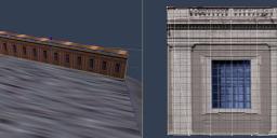
This object has one image map that repeats 12 times horizontally. The repeated image shape is not perfectly rectangular, but rather a trapezoid shape, and the long axis on the right shares vertices with the short axis of the next in sequence. I was rather puzzled how this single image map gets repeated 12 times for the length of the trapezoid, so I hightlighted the face in the 3D modeling videw, opened it in the UV editor, selected to display only the shading domain, and looked at the UV display to find no lines at all with 'wrapping' on the global tab turned off. With the 'wrapping' option turned on, it highlights a shape with the same proportions on the UV display in dark red. What does this mean?
Daz 3D is part of 
Connect
DAZ Productions, Inc.
7533 S Center View Ct #4664
West Jordan, UT 84084
Licensing Agreement | Terms of Service | Privacy Policy | EULA
© 2024 Daz Productions Inc. All Rights Reserved.
Comments
I'm sorry, I think I workd it out, but please tell me if I am wrong. With wrapping display on, the actual coordinates of the shapes in the UV map are displayed, rather than wrapping them into the 0-1 range. If wrapping mode is enabled for the object (which must be enabled/disabled for U/V coordinates the same way for all shapes in the same shading domain), then the coordinates wrap during rednering, but are not wrapped on the display. So the shapes do display when 'wrapping' display is truned off, but they may be way outside the default viewing area. So one can then move them into the viewing area, and to display the same image twelve times horizontally, one then scales the shape so it is exactly 12 units wide. I tend to think this could be easier in another UV editor, but I am going to distribute my designs from what I can make in Carrara )
I have little idea about it except for many DAZ studio imports it needs to be unticked
Firstly,.. All of the vertices in any shading domain, on any part of your model,.. should be inside the UV Grid square,. Any vertices outwith that area, are not being mapped correctly,
Use "Fit UV's" to get every vertex into the UV grid. or use a basic UV projection method
For the object images you've posted,.
I'd set your model to have "Box" UV mapping,. ,,. ...Box projection will handle that easily, and there should be no need to change the default UV layout.
In UV mapping,. the model (3D) is split and flattened into 2D, because your Image (texture map) is 2D, and the program has to "Project" that image onto the models surface.
that process is often called unwrapping,. so... wrapping coordinates, are where the 3D model is split to flatten or unwrap it,.
To do that easily, there are a bunch of "Pre-set" UV layouts, such as Spherical, Cylindrical, Box,.. with different options for alternative layouts, or different axis of projection to flatten the 3D model into 2D,
The Shader room also uses the UV projection method assigned to the object, but,.. the shader functions do not alter the UV's of the model. they simply use the UV's to apply the image, either simply "as is" or, as complex as a multi layer shader can get.
UV options such as (Tiling) "repeating an image", are actually Shader options, which are adjusting the projected image, rather than effecting the model or it's UV projection method,
UV Mapping should be relatively simple to apply and change, and the simpler the object,. the simpler it is to select and set a UV method for that object. EG: Sphere, Box, Cylinder
More complex objects demand a different approach, either creating shading domains, or,. where the user defines the edge seams where the model should be split and flattened, rather than an allowing an automatic method.
Unwrapping an object with seams will produce a UV layout which has a bunch of different sections of flattened mesh,.
these "islands" of mesh can be moved, scaled, rotated into place to create your UV map Layout and template (Wireframe IV exported to use as a texturing painting guide)
Wrapping coordinates are useful in this case where the "Seam edges" need to be identifiable to help line up patterned textures in a 2D paint program.
Hope that makes sense and helps
If you map your object outside the grid, the texture sheet will wrap around *similar to* (but not the same as) the way it wraps when you set tiling in the shader. So if your UV is twice as wide as the box, the texture wraps twice. 12 times as wide and it wraps 12 times.
Most of the time with most objects, you will want to keep the whole thing inside the box. But sometimes it is advantageous to go "outside the box". (I'll disagree with 3DAge that it's incorrect mapping). Why?
- It allows for non-integer repetitions (say, something needs to repeat 2.5 times)
- It makes for easy positioning of the repeated image - just slide the UV around
- It allows better utilisation of the texture surface (constraining a 1x12 face to within the box utilises less than 10% of the bitmap area, for example)
- it allows a single bitmap & shader to cover many objects of different sizes and still have the scale of the image correct, including both repeating and non-repeating items. This is great for things like walls, paving etc, and where you don't want everything to look like it's obviously repeating.
Just look at a few Stonemason sets - the grid is often just a tiny square in the middle of the window.
I always advocate "unfold" mapping, as it gets the proportions right more often than the other methods. You do need to define seams, but I find that simpler and quicker than mucking about trying to reshape even a deformed simple box.