Ragged appearance from Blender model
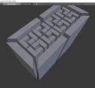
I am trying to create symbolic cutouts for windows and such. I drew the symbol represented in the daz render, making sure everything were quads, then extruded the object. I have included two pictures of the object in blender, and as can be seen from them, the edges are straight on the front the symbol. When I take it into Daz, as can be seen some of the edges become ragged. An important piece of information is that if I take the object directly into Daz, the object gets merged faces. In order to get the object to look like the one in the render, I have to remesh the object in Blender. The pictures from blender are the ones that have been remeshed, so the edges are straight there. I was hoping someone could give me so help on what may be going wrong.
Thank you for any help you can give.


Comments
Fix the n-gons. The el shaped parts are poorly modelled, connect the inside corner verts to the outside corner verts.
That's odd. Have you checked to see if you have any duplicated faces in those areas? Sometimes it will give that effect.
The ngons could be the issue, but it is hard to tell what the rest looks like.
Have you removed doubles (verts)?
Checked normals?
You really need more geometry so you have more control. You need to shade-smooth, which is great also for spotting incorrect normals; no idea if that transfers to Daz. It also might be that not all parts of the mesh are connected, even though it looks like it is.
Thank you for the assistance. I have checked the normals and they appear to be correct. I also checked for duplicate vertices and I there are none.
Thank you for pointing out that I do have some ngons. I will take care of those. The problem here though is that the parts that are ragged are not on the ngons. :) The part that is ragged appears to be part of a quad. The picture that is from the side I think shows this. Please let me know if I am misinterpreting something when I look at that.
The comment about the parts not being connected though is exactly correct. Those are all seperate pieces in the model that have been joined. The model you are seeing is not the final product. The object is to take that object and then use is as boolean to cut out a hole in an object or to have it as a raised object in another object. I was trying to start with the first step. :) So the question that arises is if the ragged parts are because my model has holes between the parts?
Thank you.
After more thinking, I decided to try something. I took the faces that were set correctly when it comes to normals, but were some of the ones that were black in the render, and reversed them. So the normals are in the wrong direction. That is what you can see in the picture where there is the green square. It is hard to see, but the color is slightly brighter on the faces that I reversed the normals. This make sense to me because the normals reversed should have the texture and lighting show up different. I then took those same faces, and put them back to the correct direction for the normal and some of the faces turned black again. This is the one with the red square. So does this give a clue as to what is happening? I can get the faces to show up in the render but only if the normals are reversed and then the wrong shade.
Thank you.
How did you start the modeling process?
Did you import an SVG drawing?
What you are showing almost looks like what you get with two overlapping faces...
Also, under the Surface properties, try adjusting the smoothing angle, down to maybe 33 or less (it's in degrees).
check your layers to see if you don't have a copy of the mesh being exported along with the layer you're looking at.
check the normals with mesh display in the tools and mark your edges sharp, add a edge split modifier and epxort as an OBJ with the split still enabled and but not appliled and out of the stack