Spline Spirals
 DBuchter
Posts: 70
DBuchter
Posts: 70
You may notice that I have been posting a lot of questions lately - I've been using C8.5 a lot lately for some work projects.
Anyway, this question refers to the Spiral function when creating Spline models.
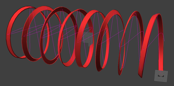
My concept is to create an 8-loop matchbox-style car track. A very simple idea. Looking at the interface for creating spirals seems very straight forward. But, the output is giving unexpected results:
As you can see from the screenshot, the spiral is being created correctly except for one (un-editable) factor, which is the actual track is also rotating, or twisting on the spline. I don't want this - I want the car track on the inside at all times. This is not an editable parameter that I can find.
Any ideas?
Daz 3D is part of 
Connect
DAZ Productions, Inc.
7533 S Center View Ct #4664
West Jordan, UT 84084
Licensing Agreement | Terms of Service | Privacy Policy | EULA
© 2025 Daz Productions Inc. All Rights Reserved.
Comments
I just had a play and got a similar result, and I'm afraid that I can't offhand think of a way to resolve this. I know this doesn't help, but I share your frustration at this because it should be relatively easy.
I figured it out. Although eight loops seemed to bork it up. Four loops seemed to work. I will upload the scene file to Dropbox to DL, as it was a bit complicated to get the angle of rotation correct.
https://dl.dropboxusercontent.com/u/7370483/Spline-Spiral-track.car
In a nut-shell I followed your workflow. After the spiral was created, I went to the Sections menu, and chose Create Multiple. I made four loops, so I figured Carrara would space the multiple cross sections evenly. So, there are the beginning and end cross sections already in place, so I had four loops, I figured I would want a minimum of eight cross sections, so I created six. 6+2=8.
Wellll.... Carrara didn't space the cross sections evenly, so I want to the last cross section and created some more. Unfortunately, this required several undo' before I figured out how many more I needed, so I have forgotten the number. It was either four or six. I discovered that it is best to create all your needed cross sections before the next step!
Once I had the cross sections were created, I used the rotate tool to rotate the cross sections so that the rails of the track kept to the inside of the loop. The mesh will distort quite a bit, so don't panic. It takes a bit of finesse, and I discovered four loops is about the limit before it starts looking like a pretzel.
My suggestion is that if you really need eight loops, to group them together, or convert to a vertex model and copy and paste two poly meshes into the VM, then bridge or weld or whatever it's called when two polymeshes are combined into one.
This is easily done in Hexagon (a companion modeler for Carrara).
Added thicken after making the object from the helix tool in Hexagon.
Less than $20 in the store with out any discounts.
Cool job!
I have Hex, but have never opened it.
It's a nice modeler with some bugs, but ranks right up there with some of the ease of work flow modelers.
I like the
"copy on support function" which takes the instance of a single object(any object or primitive, but careful as it eats memory) and makes multiple copies on a curve (spline). Very handy for jewelry, machine parts and 3D fun in general. This one is just a sphere on a helix.
Sparrowhawke has a free spring primitive that would get you started.
This seems like a perfect task for the formula modeler. Someone should be able to use the formula function, and the following links to create such a helix with minimal modeling.
http://mathhelpforum.com/advanced-math-topics/156049-cartesian-equation-helix.html
http://wiki.answers.com/Q/What_is_the_mathematical_equation_for_a_3-D_spiral_helix#slide1
http://www.ahinson.com/algorithms_general/Sections/Geometry/Parametric3DSpiral.pdf
I admit I can't.
Getting a better handle on the formula modeler is on my to do list, right after running a marathon and learning a foreign language. But if anyone can translate the helix equations at the links to Carrara's formula modeler, it could be parameterized (is that a word?). I mean that the formula function would include parameters that could be used to adjust the width of the helix, the distance between turns, etc.
edit - here is the documentation for Carrara's formula modeler http://docs.daz3d.com/doku.php/artzone/pub/software/carrara/06_six/22_using_formulas
Personally not much interest in the formulas, but as to a starting point, could you use some of the parameters in the Spline modeler's spiral preset as a starting point? Just thinking out loud.
What a cool thread this is! :coolhmm:
You're just thinking of racing along a virtual Hot Wheels track, aren't ya'? :coolsmile:
Here is a modifier/modeler trick for making a single spiral track section that can also be adjusted easily.
-In the vertex modeler, extrude a profile shape(track shape) to make a single straight track along the Y axis. Only two profile shapes on each end, no subdivisions in between.
-In the assemble room, add a 'Bend and Twist' modifier to the vertex object and set the Bend Angle value field to 360 degrees and set the Axis: to Y. You should now have a single loop shaped track.
-In the vertex modeler, select and move one of the profile shapes(track shape) on the X axis and watch the assemble preview. The track will separate and form a spiral/corkscrew section.
You're just thinking of racing along a virtual Hot Wheels track, aren't ya'? :coolsmile:You know me too well... Not fair! :ahhh:
I'm going to have to give that a try! I always forget about the modifiers.
Sparrowhawkes Spiral does not work on Mac :-(
Mic
If you are thinking of running a car along this, you're going to have some fun setting up the animation! Actually, I've just had more of a think about it and it's quite easy - parent the car to a helper at the axis and set that to rotate and move along the axis, As long as the track is modelled uniformly, the car should follow the track.
RE: formula approach. That great French site has an example. See #5 at
http://gianp.free.fr/carrara/carrara96.html
Which is described as "5 - Avec une hélice" My guess is that the French for helix is helice. Does anyone know if you could use the same formula (with a slight parameter change) to set the position of a car object in the sequencer? That would solve the issue that PhilW has raised about animating something along the helix.
and the formula does work
Its a lot of trial and error, but you can definitely do this all inside the vertex modeler with the deform options. The advantage is that it gives you a lot more control over the final mesh. However, the drawback is you either need work out the math first or be willing to futz with the deformer settings over and over until you get what you want.
P
I've still never worked with motion paths in Carrara.
Here's a quick and dirty motion path. Setup using a cube keyframed to the turns, converted to motion path and then adjusted using the handles. cube is aligned to the path but rotated manually to be upside down at the apex.
Whoops! Thought the GIF didn't work so posted one on Youtube. Sorry for the double.
http://youtu.be/Rk8rJj7l4Aw
P
I really appreciate the effort in figuring this out. Thanks to you and others - I've got some great alternatives.
I do think this is a bug and I am reporting it as such.
I do have Hex, but I just do not have any extra time to try to learn it at the moment. I'm sure Hex is a much better modeler than what is built into Carrara, but this particular issue now seems more like a bug than a limitation.- Thanks for adding
Hmm, that sounds interesting - I may try that one too.
I really appreciate the effort in figuring this out. Thanks to you and others - I've got some great alternatives.
I do think this is a bug and I am reporting it as such.
I don't know. It could be a bug, or it could be that the programmer that set up that preset simplified it to make it easier to use with a limited number of parameters to enter.
I actually kind of like the added control I got when I set up the cross sections. The issue that could be a bug in my mind is Carrara knotting up the mesh if you get too many spirals.
Bug or no, what's cool about this thread is that there are many ways to accomplish the task.
Hmm, that sounds interesting - I may try that one too.
I used this trick in my “Stupid machine” for a exercise on Carrarators forum!
http://www.youtube.com/watch?v=xokzoqdzx7U
I used to like the spline modeler, but avoid it now unless I need simple physics method shapes. The extrusion spiral preset never really worked well for me, especially with shapes like a track. My number one feature request for Carrara modeling would be to get rid of the spline modeler and feature splines in the vertex modeler. I usually end up converting most spline models to vertex anyway.
The vertex modeler isn't the easiest to make spiral shapes either atm. I usually subdivide a cylinder and extract triangulated lines from it, then sweep a shape profile along it. Unfortunately, even the vertex path sweeping isn't working right. A simple circle sweep has issues. I'm almost forced to use the modifier trick/workaround method for making most uniform type spiral shapes.
Coincidentally, I'm trying to model spirals as well for a threaded product component.
Though I do appreciate the discussion about workarounds... It's a bug. It needs to be fixed.
Some people have time to experiment - I have time to use things that work.
If it works as it was designed to work, then it is not a bug. There may well be limitations in the spline modeler that make this simple preset work the way it does. I have found that most presets are starting points, because the developer of the preset cannot possibly imagine the myriad ways that it's going to be used by every individual in every situation.
I don't think adding cross sections is a work around. I think it's more of a customization to the preset and allows for more flexibility to the modeler. We may just have to agree to disagree on this.
I think it's Geek at Play(?)...
I saw a rather nice tutorial for making threads, like on a bolt, for Hexagon.
Dude, if you try something that you think should work, by definition, and it doesn't... I'd definitely report the thing. The more stuff gets picked up like that the better, in my opinion. I also agree, however, with what ep is saying about his cross sections being a great way to increase control. There's a vast multitude of things that we have to really pry on our imagination and ingenuity to get them to work out. Such is the like of 3d modeling ;)
But in this case, it just seems to me that you should be able to set an axis to follow as the spiral is taking affect. Oh... hmmm... I bet there is. Try this:
Before applying the Spiral command, or whatever you're doing that isn't working the way you want it to, try Ctrl + Click a different axis than the one highlighted in the grids. Well... it's the grid that you click while holding down either Ctrl (Win) or Cmd(Mac). I know that this makes a big difference for Duplicate with Symmetry.